A Wings 3D Primer
Character Creation in Wings 3D (Aug 2004)
This is a legacy tutorial extracted from the Internet Archive. Due to the conversion process, some alterations have occurred.
This tutorial is a quick-run through of how to create a character model in Wings 3D, an extremely good modeling program. It’s sort of a migration tutorial for people who wish to shift from using another modeling tool, to Wings 3D. The reason why I wrote this tutorial is to serve as a primer for other tutorials focused on creating animated game characters for use in a game engine. So with Wings…Let’s fly forward!
Step 1: Be Prepared!
Assuming that you already have Wings 3D installed and functioning properly, there are a few things about it you’ll need to know before getting started.
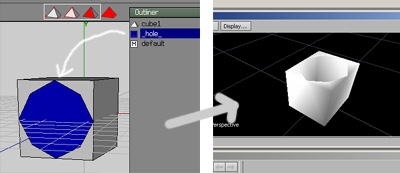
- First, Wings 3D geometry cannot exist with holes or planes; you’ll need to assign the “hole” material to remove polygons to creates holes and planes.
- Second, Wings 3D is a contextual “Action-Confirm” tool; this means that you when you perform an action (like “Rotate), you will be in that action state until you “Accept” by Left-Clicking or “Cancel” by Right-clicking.
- Third, Wings 3D has 4 main modes – Vertex, Edge, Face and Body. Each of these modes are sort of their own universe, with a unique set of menus and options. Shortcuts in one mode will not work in the other unless set to do so.
- Last, I’m not a Wings 3D guru; tread forth at your own risk.
Step 2: Set up the scene
Some people model “Ratner” style, others use the “Steed” technique; I use the Ant style of modeling. Why do I call them “styles”? It sounds cool, like a martial art discipline! Oh? You don’t think so? Fine…
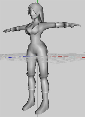
Anyway, Ant modeling involves breaking your concept art into simple primitives. You create these simple pieces in 3D and alter/tweak the geometry pieces by piece and merge them together to create the base shape. Then you go ahead and define the details. For this tutorial, I am borrowing some concept art of David Kwan’s original character, Rachel from his animation Foxgirl.
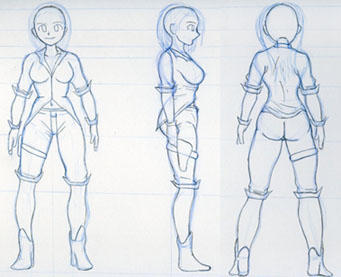
Using your favorite 2D editing program, split your concept art poses for each view. I will be using just the Front and Side views. Right-click the Viewport and click Image Plane option to add an Image Plane. You may need to rotate the Image Plane; do so by selecting it and Right-Click > Rotate > Y. Press Shift to constrain rotation and Left-Click to accept the rotational change. Right-click to cancel. Add all your reference images this way. You may also scale your Image Planes; once you have them like you want them, be sure to lock them by clicking Select > Lock Unselected. To switch views in the viewport, the buttons are X, Y, Z. Use Shift + X, Y, Z to see the views in the opposide direction. You may set up multiple viewports by clicking Window > New Geometry Window. Right-click the Viewport title to Fit the window or input a Size or hide the toolbar. Customize!
P.S. I’m fairly used to Maya’s interface and I set Wings up to resemble it. You can download my Preference file and insert it in the “Application Data > Wings3D” directory, to use my custom settings or make one of your own.
Ain’t nuthin like a Custom Wing. Next!
Step 3: Start Modeling!
Smile! You look fabulous!! — Not that kind of modeling!
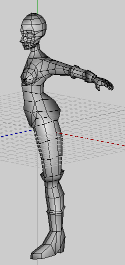
Rachel can be broken into cylinders and spheres. So go ahead and add a cylinder by Right-clicking the viewport and selecting the Cylinder option box. Set the sections to “8” and click OK. Voila! A cylinder sitting around doing nothing. Now listen up! We could extrude or bump the bottom/top face to create subdivisions, but now would be a good time to introduce you to the Number keys in Edge mode. Switch to Edge Mode and select the side edges of the cylinder.
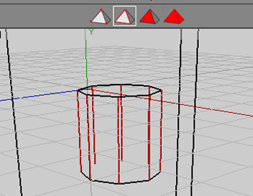
Now pressing a number key will cut the edges into that many sections. Let’s make 8 sections. Press 8! This will add 7 vertices to each edge; next, press C to Connect the vertices. This is essentially how you’d perform a Slice. Selecting two edges and pressing C will automatically cut once and connect the vertices.
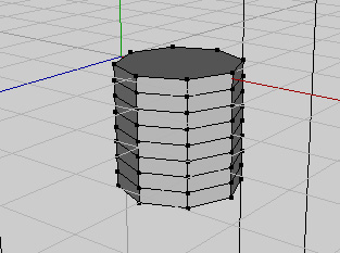
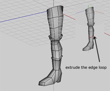
Scale the cylinder out. We’ll make a leg out of it. Start tweaking it by moving, scaling and rotating components. Press SPACE to deselect the current selection. You may also use the tweak mode under the tools menu. Add some detail by using a combination of commands like extrude and bevel. One cool feature of Wings is the Edge Loop selection. Select an edge and press L and it will select the ring of edges. You can now extrude it by Right-clicking and selecting Extrude from the menu.
Go ahead and create cylinders for the torso and arm, spheres for the chest, cubes for the hand, etc. Modify each piece (remember to hide/lock what you don’t need) and get them ready for the combination!
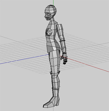
Let’s our models combine! Proceed!
Step 4: Bridging the Gap
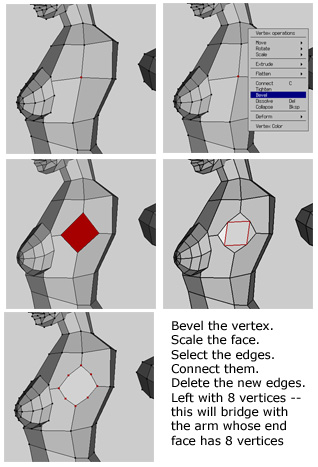
Combining separate meshes in Wings 3D is done by Bridging faces. One thing to keep in mind is that the faces should have the same number of vertices! So you’ll need to cut edges appropriately.
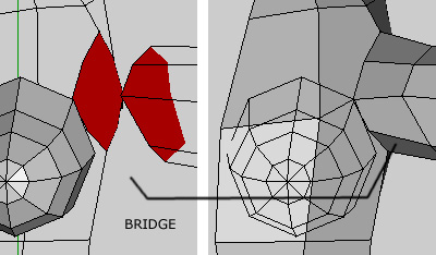
Select the two faces you wish to combine the two pieces with. Right-Click > Bridge the two meshes.
Repeat until you have joined all the needed parts. At this point you’ll have made the basic shape of the model and are ready to add details.
Step 5: Mirror Mirror!
Now that you have the base shape, you are ready to create a Mirror and refine your model till kingdom come. Select the face along which you’ll create a Mirror. Make sure it’s flat; Right-click and Flatten along the correct axis. Then go to Tools > Virtual Mirror > Create; essentially you have replicated the other side and now any changes will be reflected on both sides. This lets you have a bigger picture yet modify only one side.

You may perhaps want to further modify the model to remove some of the symmetry. You could Freeze the mirror and go ahead. Or you could do it after you have laid out the UV Map. This way you only need to map one side and upon Mirroring, the UVs for the other side are laid out for you. Whatever your choice, it’s time for UV Mapping
U V W X Y Z - Keep Going!
Step 6: Auto UV
Wings 3D’s UV functionality is pretty nifty, though it’s not completed yet. So there are a few quirks you will come across. One thing to consider is you can’t move the single UVs around yet. This may lead to some inefficiencies in your UV Map. If you don’t have a problem with that, read on. If you do, you may export your model and layout the map with something else.
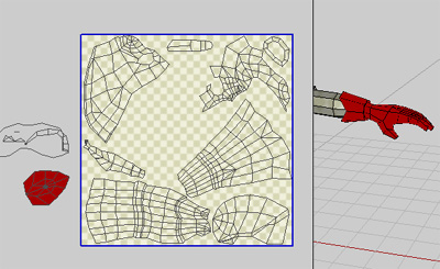
Switch to Body mode and do a Right-click > UV Mapping and what will look like another perspective viewport will pop up. Remember the X, Y, Z view commands work here as well. Press O to switch from Perspective to Orthographic. If you have applied shaders to your model, be careful, as Auto UV breaks out UV shells based on shaders. The theory to consider is to break your complex shapes into primitive shells. For example, the leg can be mapped like a cylinder. Deja vu? Once you can mentally picture this, apply Auvchart colors to the faces in AutoUV viewpart by Selecting the faces and Right-clicking and selecting an Auvchart color. A tip for selecting Faces is to press F to select adjacent faces.

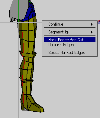
Once you’re done with that, it would be a good idea to set where you want your seams to be at. I usually put it where the audience won’t see it most. For example, the legs will have it on the side towards the midline. Select the needed edges and Right-click > Mark Edges for Cut. This will create a green line.
Are you ready? Remember there’s no turning back. No amount of saving will save you! Right-Click > Continue > Folding to break the shells out!
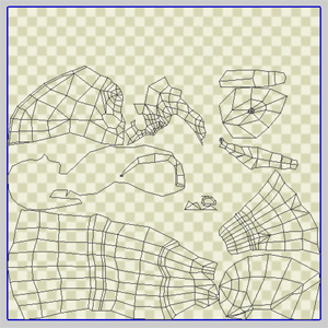
Goodness gracious, Aunt Sabelle exclaimed! Not to worry, there were some errors. But they can be fixed with a pseudo-planar mapping trick. But first go ahead and try and make it look as pretty as you can. Scale, rotate, move, arrange the UV shells. A suggestion for your digestion is to move the error shells out of the map so you don’t get confused. Anyway, let’s consider the error with the glove in the follow pic.
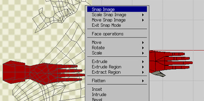
Rasp! Looks like it was unfolded without a marked cut. No worries, though. Someone wrote a sweet “Snap Image” tool which may just save our behinds. Execute Snap mode via the Tools > Snap Image; this functions like a camera planar map. So you can select the top part of the glove, adjust the camera angle and Right-click > Snap Image. You can break your shells up this way.
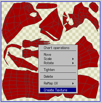
Step 7: Texture Workflow
Time to export your UV Map. Right-click the UV Map and click Create Texture. The image lands up in your outliner and you can export it from there, by Right-clicking and clicking Export. Take it into your favorite texturing tool and go nuts. To attach the texture to the model, create a new material and import the texture image. In the outliner, drag the image onto the material and set it to diffuse. Set the material to the mesh.
As you texture, you can switch back to Wings and refresh this image to update the texture on the model. When you are done modeling and texturing, you are ready to export your model to an animation program or a renderer. You are invited to read the follow-up tutorials on MotionBuilder Integration and CharacterFX integration.
Thanks for going through this tutorial. Any questions, errors, critiques? Please send some feedback.
Rachel! Foxgirl!